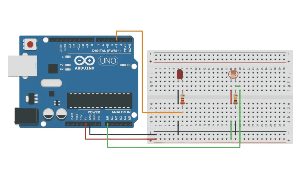
How to use a Photoresistor (LDR) with Arduino

Photoresistors, also known as LDRs (Light Dependent Resistors), are simple, inexpensive, and versatile light sensors. They detect the amount of light in the environment and are perfect for robotics, home automation, and DIY projects.

📑 How it Works

A photoresistor is an electronic component whose resistance changes based on the light it receives:

  • When light increases, its resistance decreases.

  • When light decreases, its resistance increases.

By connecting it to an Arduino through an analog input pin, we can read a numeric value between 0 and 1023 that reflects the light level. This makes it ideal for automatic lighting, light-following robots, ambient light detection, and more.

 📝 Required Components

To build this project, you’ll need:

  • 1 × Arduino Uno (or compatible board)
  • 1 × Photoresistor (LDR)
  • 1 × 10 kΩ resistor
  • 1 × LED
  • 1 × 220 Ω resistor (for the LED)
  • Breadboard
  • Jumper wires

🔌 Wiring Diagram

📦 Complete Arduino Code

Here’s the code 

				
					// Pin definitions
int pinLDR = A0;
int pinLED = 3;

void setup() {
  Serial.begin(9600);        // Start serial communication
  pinMode(pinLED, OUTPUT);   // Set the LED pin as output
}

void loop() {
  int lightValue = analogRead(pinLDR);  // Read light level
  Serial.println(lightValue);           // Print value to Serial Monitor

  if (lightValue < 500) {               // If light is below threshold
    digitalWrite(pinLED, HIGH);         // Turn on the LED
  } else {
    digitalWrite(pinLED, LOW);          // Turn off the LED
  }

  delay(200);                           // Wait 200 ms
}


🔎 Breaking down the Code

Let’s review the code section by section:

Variable Declarations

We define two variables to associate Arduino pins with the components.

				
					int pinLDR = A0;
int pinLED = 13;


Setup Function
				
					void setup() {
  Serial.begin(9600);
  pinMode(pinLED, OUTPUT);
}


The setup() function runs once when the Arduino powers up:

  • Starts serial communication at 9600 baud.

  • Sets the LED pin as a digital output.

Main Loop
				
					void loop() {
  int lightValue = analogRead(pinLDR);
  Serial.println(lightValue);


Continuously reads the analog value from pin A0 (0–1023) and prints it to the Serial Monitor.

				
					if (lightValue < 500) {
    digitalWrite(pinLED, HIGH);
  } else {
    digitalWrite(pinLED, LOW);
  }


If the light value is below 500 (dark environment), the LED turns on. Otherwise, it stays off.
You can adjust the 500 threshold according to your environment and sensor sensitivity.

				
					  delay(200);
}


Pauses the program for 200 milliseconds before repeating the reading and control cycle.

📊 Interpreting Light Values

  • Low values (close to 0): very bright light

  • High values (close to 1023): low light

The threshold value of 500 can be changed to suit your needs.

en_US