
Controlling a simulated robot as if it were real — that’s the power of ROS Control. In this guide, we’ll see how to properly configure the URDF model so ROS can “command” the simulated motors of our BumperBot.
Imagine building a robot with real motors, sensors, and joints. You wouldn’t want to manually write low-level code to drive every motor or calculate PID loops, right? That’s exactly where ROS Control comes in.
ROS Control is a framework in ROS (Robot Operating System) that separates your robot’s high-level logic from the low-level hardware interfaces. It enables:
Real-time controllers (e.g., velocity, position, effort)
Modular configuration of actuators and sensors
Easy switching between simulation and real hardware
Whether you’re simulating a robot in Gazebo or controlling a physical machine, ROS Control gives you:
A unified interface to interact with joints
A standardized way to load controllers
The ability to use the same code in both simulation and real-world robots
In this tutorial, you’ll learn how to enable ROS Control in Gazebo by modifying your robot’s URDF/Xacro model and linking it to Gazebo’s physics engine.
Use ROS Control to drive the motors of the BumperBot robot simulated in Gazebo, by modifying the URDF/Xacro file and adding the necessary plugin.
ROS installed (ROS Noetic or Melodic)
Ubuntu 20.04
BumperBot project set up
Gazebo installed
For mobile robots, controlling wheel velocity is key. In ROS Control, this is done using the VelocityJointInterface, which allows us to send target speeds (in radians/sec) to each wheel joint.
📌 A controller sends velocity commands → hardware interface processes it → actuator (motor) executes it → joint moves in simulation or real world.
Open the file bumperbot_gazebo.xacro in Visual Studio Code.
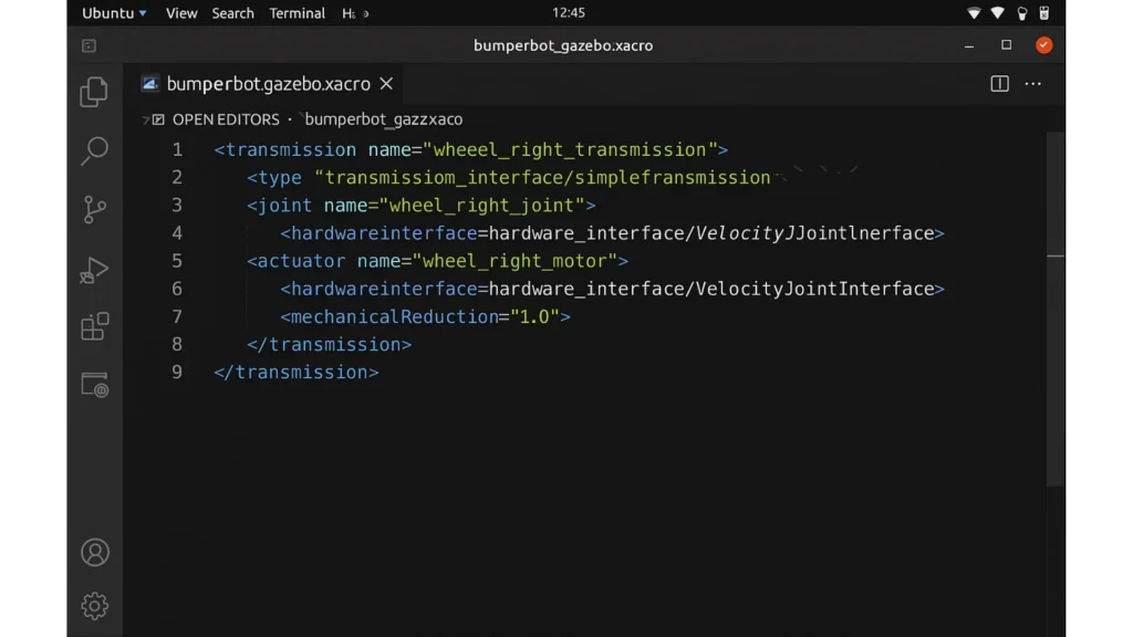
To control a joint with ROS, you need to define a transmission. Let’s start with the right wheel.
					<transmission name="wheel_right_transmission">
  <type>transmission_interface/SimpleTransmission</type>
  <joint name="wheel_right_joint">
    <hardwareInterface>hardware_interface/VelocityJointInterface</hardwareInterface>
  </joint>
  <actuator name="wheel_right_motor">
    <hardwareInterface>hardware_interface/VelocityJointInterface</hardwareInterface>
    <mechanicalReduction>1.0</mechanicalReduction>
  </actuator>
</transmission>
type: Transmission type (SimpleTransmission is the most common)
joint: Name of the joint to control
actuator: Motor associated with the joint
hardwareInterface: Defines the control mode (velocity, position, effort)
mechanicalReduction: Ratio between motor shaft and wheel (1.0 = direct)
Just copy and change the names:
					<transmission name="wheel_left_transmission">
  <type>transmission_interface/SimpleTransmission</type>
  <joint name="wheel_left_joint">
    <hardwareInterface>hardware_interface/VelocityJointInterface</hardwareInterface>
  </joint>
  <actuator name="wheel_left_motor">
    <hardwareInterface>hardware_interface/VelocityJointInterface</hardwareInterface>
    <mechanicalReduction>1.0</mechanicalReduction>
  </actuator>
</transmission>
To allow Gazebo to simulate the motor behavior, we must include the gazebo_ros_control plugin:
					<gazebo>
  <plugin name="gazebo_ros_control" filename="libgazebo_ros_control.so">
    <robotSimType>gazebo_ros_control/DefaultRobotHWSim</robotSimType>
    <legacyModeNS>true</legacyModeNS>
  </plugin>
</gazebo>
filename: Shared library file of the plugin
robotSimType: Interface Gazebo uses to simulate the hardware
legacyModeNS: Enables compatibility with legacy namespace structure
Save the bumperbot_gazebo.xacro file
Open a new terminal:
cd ~/bumperbot_ws
source devel/setup.bash
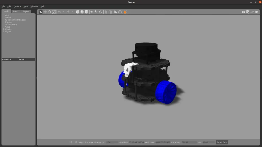
roslaunch bumperbot_description gazebo.launch
We have successfully configured ROS Control for the simulated BumperBot robot. Now we can use standard ROS controllers to send velocity commands to the wheels — just like controlling a real robot!
Assemble your robot and get started to learn Robotics!