
Controlling the speed and direction of a DC motor precisely is essential for many robotics and automation projects. In this tutorial, we will learn how to use a PID controller to regulate the velocity of two DC motors connected through an L298N driver, with feedback from wheel encoders.
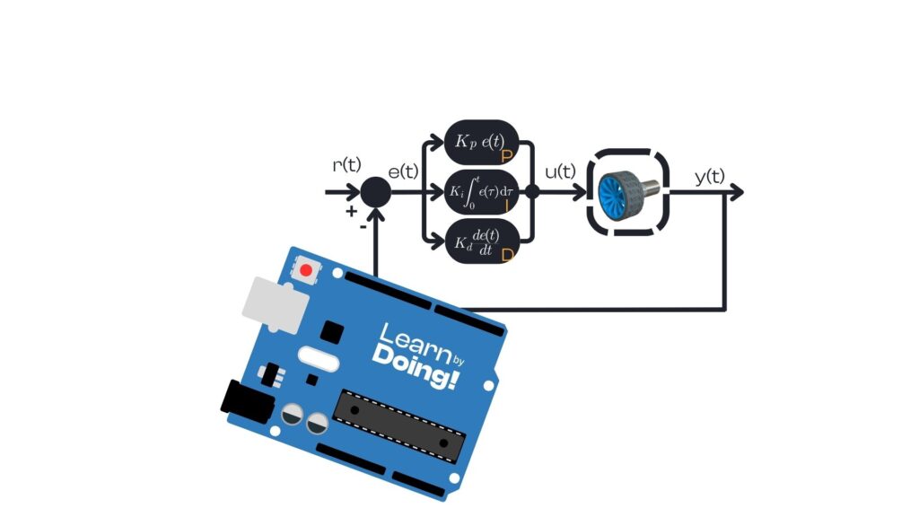
DC motors are naturally fast, but they lack precision when it comes to speed control. Without feedback, any change in load or friction causes speed variations. A PID (Proportional-Integral-Derivative) controller helps correct this by adjusting motor commands based on the error between desired and measured velocity. The result is a smoother, more accurate movement — essential for robotics applications like mobile robots or line followers.
Arduino Uno
L298N H-Bridge motor driver
Two DC motors with encoders
Power supply (e.g., 12V battery)
PID_v1 Arduino library
Serial monitor for command interface
The robot uses:
Encoders for real-time velocity feedback
L298N to drive the motors
PID algorithm for speed control
The Arduino reads velocity commands from the serial interface (in rad/s), computes the motor speed using encoders, and adjusts PWM outputs accordingly. Each motor has its own PID controller with fine-tuned parameters.
We use the PID_v1 library to handle PID computations. Here’s an overview of the main blocks of the sketch.
					#define L298N_enA 9
#define L298N_enB 11
#define L298N_in4 8
#define L298N_in3 7
#define L298N_in2 13
#define L298N_in1 12

#define right_encoder_phaseA 3
#define right_encoder_phaseB 5
These pins connect the motors and encoders to the Arduino.
					double right_wheel_cmd_vel = 0.0;
double right_wheel_meas_vel = 0.0;
double right_wheel_cmd = 0.0;

double Kp_r = 11.5;
double Ki_r = 7.5;
double Kd_r = 0.1;

PID rightMotor(&right_wheel_meas_vel, &right_wheel_cmd, &right_wheel_cmd_vel, Kp_r, Ki_r, Kd_r, DIRECT);
Each motor has its own PID loop with independent tuning. Similar setup applies to the left motor.
					attachInterrupt(digitalPinToInterrupt(right_encoder_phaseA), rightEncoderCallback, RISING);
attachInterrupt(digitalPinToInterrupt(left_encoder_phaseA), leftEncoderCallback, RISING);
Each time the encoder triggers a pulse, we increment the counter and update the sign depending on direction.
The sketch interprets serial commands of the form:
rp1.25,ln0.75,r/l: right or left motor
p/n: direction (positive/negative)
Value: speed in rad/s
This lets us test motor control via serial without a GUI.
Every 100ms, the velocity is calculated based on encoder counts:
right_wheel_meas_vel = (10 * right_encoder_counter * (60.0/385.0)) * 0.10472;
Then, the PID controller computes a new PWM command:
					rightMotor.Compute();
analogWrite(L298N_enA, right_wheel_cmd);
If the command is 0, it cuts off PWM to avoid inertia-related drift.
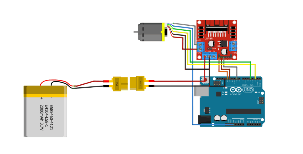
(Insert image here: schematic of Arduino + L298N + encoders)
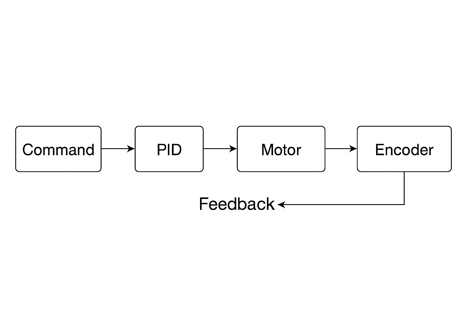
(Insert image here: flow diagram of the control loop — command -> PID -> motor -> encoder -> feedback)
(Insert image here: screenshot of serial monitor showing rp1.00,ln1.00 commands and feedback)
This setup provides an effective way to control DC motors with precision using only Arduino and basic hardware. It lays the foundation for more advanced techniques such as odometry, trajectory tracking, and SLAM.
Tuning the PID values for your own motors is crucial: start with low values and increase until stable. Always monitor your motor temperature and avoid overdriving.
Assemble your robot and get started to learn Robotics!