
When working with ROS 2, sooner or later you reach the point where you must describe the physical structure of your robot in detail.
This is a fundamental requirement: every component of the ROS 2 ecosystem—RViz, Gazebo, Nav2, controllers, planning libraries—needs to know the dimensions, connections, and shape of each element that makes up the robot. To achieve this, ROS 2 uses a standard description format: URDF, the Unified Robot Description Format, an XML-based language that represents a robot as a collection of rigid parts connected by mechanical joints.
Understanding URDF means understanding how ROS 2 interprets your robot, how it builds its kinematic structure, and how it uses that structure for visualization, simulation, and control.
This article walks you through the fundamental concepts behind the URDF format and guides you through the practical creation of a complete robot model, as presented in the associated laboratory activity.
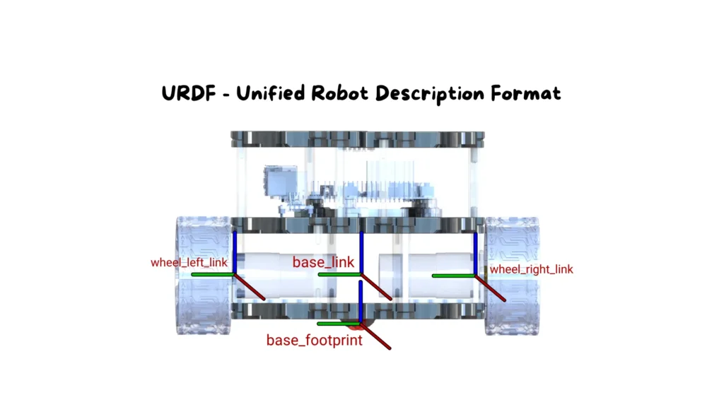
At the core of URDF is a model organized as a kinematic tree. Every physical component of the robot is represented by a link—a rigid body, a sensor, a wheel, a base, or any geometric element.
The connections between these links are defined by joints, which specify how two elements are attached to one another. A joint may be fixed, rotational, prismatic, or continuous, depending on the type of motion allowed.
This tree structure always starts from a single origin: the root link, the first link defined in the file, from which all other components branch out.
Each link may include multiple types of information: a geometry that defines its shape, a material to control its appearance in RViz, and physical properties required for realistic simulation in Gazebo. Joints, on the other hand, define the transformations between reference frames, specifying positions, orientations, and mechanical constraints.
When transitioning to real robotic systems, URDF becomes indispensable. Every motion controller, every dynamics simulation, every navigation algorithm depends on the correctness of the model. This is why URDF is not a cosmetic detail—it is the structural foundation of any robot built in ROS 2.

Now let’s move to the practical component.
In the lab we construct a small robot model consisting of a base and a LiDAR sensor mounted on top of it. The example is intentionally simple: the goal is to help you understand the underlying logic of URDF without introducing unnecessary complexity.
Once you grasp these concepts, you can scale the model to more sophisticated robots—exactly as done in professional robotics projects.
Below you will find the complete URDF file used in the lab, followed by a detailed breakdown, block by block.
					<?xml version="1.0"?>
<robot name="my_robot">

  <link name="base_link">
    <visual>
      <geometry>
        <box size="0.3 0.3 0.15"/>
      </geometry>
      <material name="blue"/>
    </visual>
  </link>

  <link name="lidar_link">
    <visual>
      <geometry>
        <cylinder length="0.05" radius="0.05"/>
      </geometry>
      <material name="red"/>
    </visual>
  </link>

  <joint name="lidar_joint" type="fixed">
    <parent link="base_link"/>
    <child link="lidar_link"/>
    <origin xyz="0 0 0.2" rpy="0 0 0"/>
  </joint>

</robot>
					<?xml version="1.0"?>
<robot name="my_robot">
This opening declares that the file follows XML syntax and introduces the main container for the entire URDF description. The <robot> tag encapsulates every structural element and assigns a unique name to the model. ROS uses this name to identify the robot within tools such as RViz, Gazebo, and the TF transform system. It is effectively the starting point of the entire model hierarchy.
					<link name="base_link">
  <visual>
    <geometry>
      <box size="0.3 0.3 0.15"/>
    </geometry>
    <material name="blue"/>
  </visual>
</link>
This block defines the root link, the foundational element from which the entire robot structure is built.
Inside the <visual> tag, we specify how the link should appear visually.
The <geometry> section represents its shape; in this case, a rectangular box measuring 0.3 × 0.3 × 0.15 meters. This is a common simplified representation of the robot’s main body.
The <material> tag assigns a color to the link, which is extremely useful during RViz visualization to visually distinguish different robot components, even though it does not affect physics or simulation behavior.
					<link name="lidar_link">
  <visual>
    <geometry>
      <cylinder length="0.05" radius="0.05"/>
    </geometry>
    <material name="red"/>
  </visual>
</link>
This link corresponds to the 2D LiDAR sensor mounted on the robot. The cylindrical geometry matches the shape of many commercial LiDAR units, making the model easier to interpret visually.
As before, the <visual> section defines how the sensor appears, while the <material> tag assigns a different color to distinguish it from the base.
This visual distinction becomes especially valuable when working with more complex models containing multiple sensors or articulated components.
					<joint name="lidar_joint" type="fixed">
  <parent link="base_link"/>
  <child link="lidar_link"/>
  <origin xyz="0 0 0.2" rpy="0 0 0"/>
</joint>
This block defines the joint that attaches the LiDAR to the robot’s base.
The joint type fixed indicates that there is no relative motion between the two links: the sensor is rigidly attached to the robot both in visualization and in simulation.
The <parent> and <child> tags clarify the relationship between the links, explicitly defining which one supports the other.
The <origin> element specifies the transform applied to the child link relative to the parent. Here, xyz="0 0 0.2" places the LiDAR exactly above the center of the base at a height of 20 cm, while rpy="0 0 0" ensures no rotation is applied.
This offset is critical because it determines how the LiDAR frame is positioned within the TF tree used throughout ROS.
</robot>
This closing tag marks the end of the robot definition. At this point, ROS 2 can fully interpret the URDF model, generate the TF frame hierarchy, display the robot in RViz, and—if needed—simulate it in Gazebo.
After creating the file, the next step is verifying that everything is defined correctly. Loading the URDF into RViz is an excellent way to check frame alignment, link placement, and overall robot structure.
This mirrors the logic used in the articles on lifecycle nodes, where visualization was essential to understand the current state of the system.
In real-world projects, this validation step is crucial: even a small mistake in a joint definition can lead to unstable behavior during simulation or navigation.
URDF represents the “body” of the robot inside the ROS 2 ecosystem. In this article, you learned how to construct a complete model, how to interpret it block by block, and how to leverage its geometric and structural information in visualization tools.
However, this is only the first step.
In professional robotic systems, a simple URDF quickly evolves into more advanced Xacro structures, integrates dynamic plugins, incorporates precise physical parameters, and becomes part of a larger workflow that connects simulation, control, and navigation.
If you want to learn how to build complete, professional robotic systems—not just simple lab examples—the full ROS 2 course provides structured lessons, ready-to-use materials, step-by-step guidance, and practical tools that will make you fully autonomous in every stage of development.
Assemble your robot and get started to learn Robotics!