
DIY Relay Oscillator: Building an Electromechanical Flasher with a Relay and a Transistor
- Tutorials
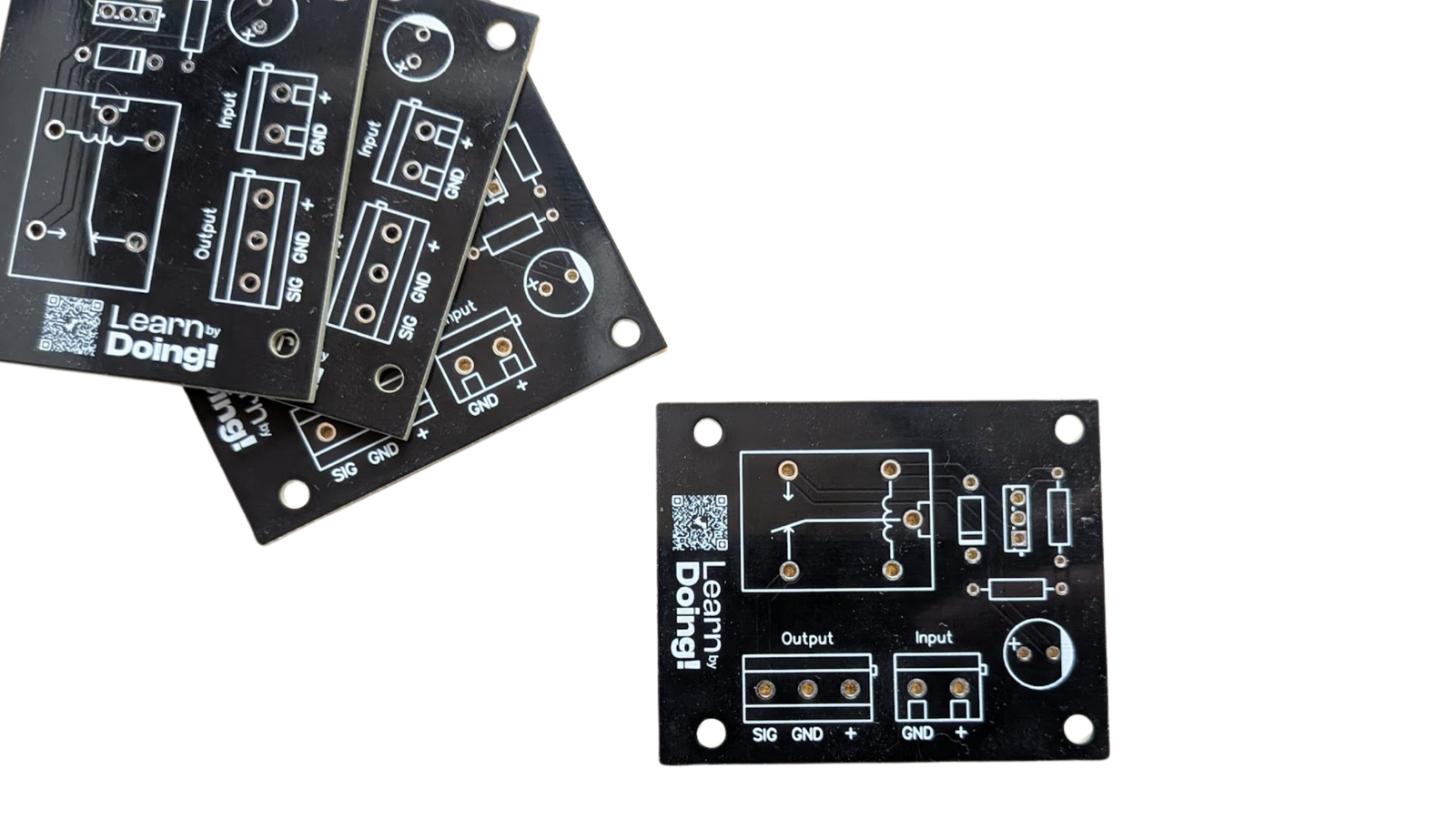
When people think of an “oscillator,” their mind usually jumps straight to a 555 timer, a microcontroller blinking an LED, or a quartz crystal. Long before these became the standard approach, electromechanical relay oscillators were a common and elegant solution for generating periodic signals, driving flashers, or switching loads in a repeating cycle.
The project we are analyzing today is a great educational example of this principle: a relay oscillator that continuously toggles its output between VCC and GND, using only a handful of passive components, a power transistor and an electromechanical relay.
It is a perfect project for anyone who wants to truly understand what happens inside a circuit, without the layer of abstraction that firmware usually provides.
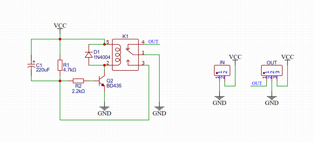
The Circuit Diagram
How it Works
The heart of the circuit is a cycle of capacitor charging, relay activation, feedback discharge and relay deactivation, repeating indefinitely. Let’s walk through it step by step.
The Charging Phase
When the supply voltage VCC is applied, capacitor C1 (220 µF) starts charging through resistor R1 (4.7 kΩ). This is a classic RC network: the voltage across C1 rises exponentially, following the well known time constant formula:
τ = R1 × C1
With these values: τ = 4700 Ω × 220 µF ≈ 1.034 seconds.
The Trigger
As the voltage across C1 rises, it is applied (through base resistor R2, 2.2 kΩ) to the base of power NPN transistor Q2 (BD435). Once the voltage reaches the transistor’s conduction threshold, Q2 enters saturation and starts conducting current, energizing the coil of relay K1.
The Feedback Loop
This is the most interesting part of the design. Relay K1 does not only switch the external load: one of its internal contacts is wired back into the RC network. When the relay switches state, this contact does one of the following:
- discharges capacitor C1,
- breaks the “latch” that was keeping the transistor’s base biased.
Either way, the effect is the same: transistor Q2 turns off, the relay coil de energizes, the relay returns to its rest position, and the charging cycle of C1 starts all over again.
It is exactly this mechanism of self interruption through mechanical feedback that turns a simple monostable timer into a continuous astable oscillator, without needing a second timer or any digital logic.
The Transistor protection
Every time an inductive load such as a relay coil is de energized, it generates a reverse voltage spike that could damage the transistor. For this reason the circuit includes a flyback diode 1N4004 (D1), placed in antiparallel across the coil, which absorbs this spike and protects Q2.
The Output
The final result is available at the OUT terminal: a waveform that continuously toggles between VCC and GND, at a frequency determined by the RC time constant and the mechanical timing of the relay. This makes it suitable for:
- Low frequency flashing lights
- Automated test cycles on external loads
- Periodic switching of loads such as pumps, fans or motors during durability testing
- Educational demonstrations of feedback and oscillation
Bills of Materials (BOM)
| Ref. | Component | Value | Function |
|---|---|---|---|
| R1 | Resistor | 4.7 kΩ | Charges C1 (time constant) |
| R2 | Resistor | 2.2 kΩ | Limits base current into Q2 |
| C1 | Electrolytic capacitor | 220 µF | Timing / RC network |
| Q2 | Power NPN transistor | BD435 | Drives the relay coil |
| D1 | Diode | 1N4004 | Flyback protection on the coil |
| K1 | Electromechanical relay | — | Switching and feedback element |
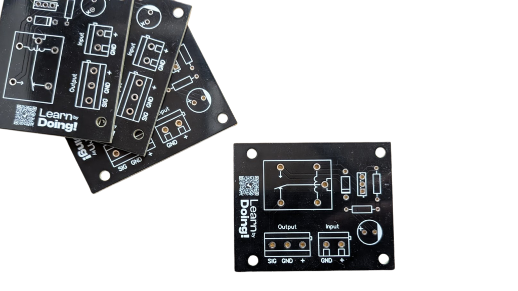
The PCB
How to Change the Oscillation Frequency
One of the most educational aspects of this project is that the frequency is not fixed. It depends entirely on the RC network (R1 and C1) and on the mechanical pull in and drop out timing of the chosen relay. Here are some practical suggestions for experimenting:
- Increase C1 to get a longer charging time and a slower oscillation.
- Decrease R1 to get a faster charge and a quicker oscillation (be careful not to go too low, to avoid stressing the relay with excessively frequent switching).
- Change the relay since different relays have different pull in and drop out times, which combine with the RC constant and affect the overall duty cycle.
This is an excellent hands on exercise to understand, using nothing more than a multimeter or an oscilloscope, how the circuit’s behavior changes as these parameters are adjusted. It is a perfect bridge between RC network theory and the real, mechanical behavior of the system.
Practical and Safety Considerations
Being an electromechanical component, the relay introduces physical wear. Unlike a solid state oscillator, this circuit is not designed to run at high frequencies or for an unlimited number of cycles. It is best suited for low frequency applications such as flashing or cyclic testing.
If the relay is used to switch AC loads or hazardous voltages on the contact side, it is essential to respect proper isolation distances and the electrical safety standards appropriate for the driven load.
Always check the maximum voltage and current rating of the chosen relay coil, in order to correctly size Q2 and the power supply.
PCBWay
This PCB was manufactured thanks to PCBWay, who kindly provided the boards for free. If you would like to try their PCB manufacturing service, fast, affordable and of excellent quality, you can sign up using our coupon code and get $5 of credit on your account, while also directly supporting our work:
Conclusion
The DIY Relay Oscillator is a small masterpiece of simplicity: with only six components it demonstrates fundamental concepts of analog electronics, including RC networks, transistor biasing, protection from inductive loads and, most importantly, mechanical feedback as a timing mechanism.
It is exactly the kind of project that is perfect for learning by doing: few components, a lot to understand, and a result, the rhythmic click of the relay, that you can literally hear before you even see it.

