
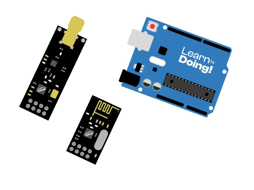
In the world of robotics and IoT, wireless communication between devices is essential. One of the most affordable and efficient modules for transmitting data over a 2.4GHz radio frequency is the nRF24L01. In this tutorial, we’ll explore how it works, the difference between its versions, and how to use it with Arduino.
The nRF24L01 is a wireless transceiver module operating on the 2.4GHz ISM band (free and license-exempt). It can communicate with other nRF24 modules up to a distance of:
100 meters in open space for the standard PCB antenna version
1 km or more with the external antenna PA+LNA version
| Version | Range | Stability | Power Consumption | Cost |
|---|---|---|---|---|
| Without antenna (PCB) | up to 100m | Medium | Low | Affordable |
| With external antenna (PA+LNA) | up to 1000m | High | Higher | More expensive |
Recommendation:
If your project involves obstacles or distances above 50-100m, it’s better to use the external antenna version.
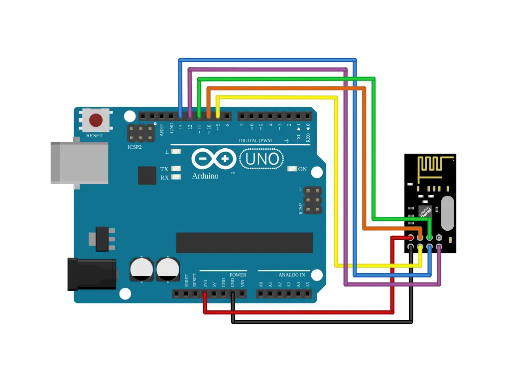
The nRF24L01 uses the SPI protocol to communicate with Arduino. It can operate both as a transmitter and a receiver, allowing data exchange between two or more devices.
Transmitter (TX): sends data to one or more receivers
Receiver (RX): listens for incoming data from transmitters
2 x Arduino Uno (or compatible board)
2 x nRF24L01
Jumper wires
Here’s the code to send the data:
					#include <SPI.h>
#include <nRF24L01.h>
#include <RF24.h>

RF24 radio(9, 10); // CE, CSN

const byte address[6] = "00001";

void setup() {
  Serial.begin(9600);
  radio.begin();
  radio.openWritingPipe(address);
  radio.setPALevel(RF24_PA_HIGH);
  radio.stopListening();
}

void loop() {
  const char text[] = "Hello World";
  radio.write(&text, sizeof(text));
  Serial.println("Message sent");
  delay(1000);
}
Here’s the code to receive the data:
					#include <SPI.h>
#include <nRF24L01.h>
#include <RF24.h>

RF24 radio(9, 10); // CE, CSN

const byte address[6] = "00001";

void setup() {
  Serial.begin(9600);
  radio.begin();
  radio.openWritingPipe(address);
  radio.setPALevel(RF24_PA_HIGH);
  radio.stopListening();
}

void loop() {
  const char text[] = "Hello World";
  radio.write(&text, sizeof(text));
  Serial.println("Message sent");
  delay(1000);
}
Let’s review the code section by section:
Includes the necessary libraries for SPI and nRF24 functionality.
					#include <SPI.h>
#include <nRF24L01.h>
#include <RF24.h>
Defines the CE and CSN pins used for communication.
RF24 radio(9, 10);
Defines the CE and CSN pins used for communication.
const byte address[6] = "00001";
Sets a shared communication channel for both TX and RX modules. You can change this value to create independent connections.
					radio.begin();
radio.openWritingPipe(address);
radio.setPALevel(RF24_PA_HIGH);
radio.stopListening();
begin() starts the module
openWritingPipe() sets the sending channel
setPALevel() sets transmission power (LOW, MEDIUM, HIGH, MAX)
stopListening() configures the module as a transmitter
					radio.begin();
radio.openReadingPipe(0, address);
radio.setPALevel(RF24_PA_HIGH);
radio.startListening();
openReadingPipe() opens the receiving channel
startListening() sets the module as a receiver
radio.write(&text, sizeof(text));
					if (radio.available()) {
  radio.read(&text, sizeof(text));
}
The transmitter sends data, while the receiver checks if data is available and reads it into a buffer.
Assemble your robot and get started to learn Robotics!